Specification guide
How to Compare UAV Gimbal Camera Specifications
A repeatable way to normalize stabilization, optics, installed mass, power and interface claims before a technical RFQ.
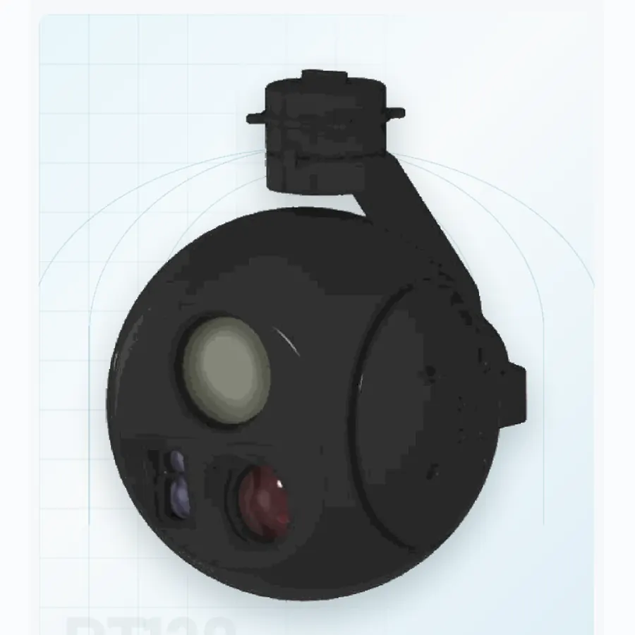
Two industrial UAV gimbal cameras can carry similar headlines—three-axis stabilization, optical zoom, thermal imaging and onboard tracking—yet behave very differently when installed on the same aircraft. A specification sheet is a useful starting point, but the numbers rarely describe identical test conditions.
For an unmanned aerial vehicle (UAV) original equipment manufacturer (OEM), system integrator or technical buyer, the practical question is not “Which camera has the most impressive specification?” It is “Which configuration can provide the required image detail, stable pointing and dependable data on this aircraft, under this mission’s operating conditions?”
This guide introduces a consistent, evidence-based way to compare stabilized electro-optical (EO), infrared (IR) and combined EO/IR payloads. It explains which values are directly comparable, which need additional context and which claims deserve a bench or flight test before purchase.
Start with a Mission-Based Specification Baseline
Define the observable outcome before choosing a sensor
A power-line inspection task may require a small fitting to be distinguishable at a known stand-off distance. A roof inspection may emphasize wide-area coverage. A long-endurance vertical take-off and landing (VTOL) platform may have tighter power and mass limits than a large multirotor. These different outcomes cannot be reduced to one camera ranking.
Before opening product brochures, record the smallest feature that matters, working distance, expected illumination, acceptable revisit time, flight condition, airframe payload allowance, data-link capacity and whether the result must be a live video, an image record or a measurement. If the deliverable is quantitative temperature data, the thermal subsystem must be checked for appropriate radiometric functions rather than merely for a visible heat-map display.
Use the same comparison boundary for every candidate
Define what is included in each quoted mass and power figure: camera head, gimbal assembly, isolation mount, connector, cables, optional processing board and any external video or control hardware. The system integrator should compare installed, operational configurations, not the lightest published subassembly against a complete competing payload.
The same rule applies to sensor variants. A vendor may quote EO zoom for one configuration and thermal resolution for another. Unless the features coexist in the exact proposed model, they do not belong in a single supposed all-in-one specification.
Read Mechanical Stabilization Specifications Carefully
2-axis and 3-axis describe architecture—not measured image quality
Axis count identifies a mechanical design characteristic. Actual pointing performance depends on sensor feedback, control-loop behavior, balancing, vibration isolation, motion envelope and airframe disturbance. A well-matched lightweight system can be the sensible choice for a smaller UAV, while additional controlled axes may benefit missions with more complex attitude changes. The correct selection requires the same test task and installed conditions. Compare a three-axis compact gimbal with a two-axis micro pod only under the same installed conditions.
Separate pointing accuracy, jitter and repeatability
These terms may represent different quantities. Pointing accuracy concerns deviation from a commanded or reference direction. Jitter describes variation of the line of sight over time. Repeatability asks whether the gimbal returns to a comparable orientation across trials. A single figure labelled “stabilization accuracy” is not enough unless the vendor defines what was measured, over which frequency band, with what excitation and at what zoom setting.
Ask whether the figure was measured on a fixed bench, vibration table or aircraft; whether the camera was operating and recording; and how results are summarized. For reproducible comparison, record test method and uncertainty rather than relying on one best-case clip. NIST explains why repeatability and reproducibility require documented measurement conditions [1].
Verify travel limits, control rates and target reacquisition
Yaw and pitch travel, continuous-rotation capability, maximum commanded rate and transition behavior affect real use. A fast slew specification does not prove smooth capture at high zoom, while a quiet stabilized shot does not prove rapid reacquisition after a turn. Ask for both a slow-tracking sequence and a repeatable commanded move across the intended angular range.
The existing two-axis and three-axis gimbal collection provides a useful route for comparing mechanical configurations, but model-specific ranges and stabilization figures still require current datasheets.
Compare Imaging Detail: EO Resolution, Optics and Zoom
Pixels, focal length and field of view solve different problems
Sensor pixel count sets an upper limit on sampled image detail; it does not guarantee that a small target will be recognizable. Focal length and detector size influence the field of view (FOV), while lens quality, focus, exposure and image processing determine how much contrast remains at fine spatial detail. Long zoom can enlarge a feature on screen but also makes pointing motion and air turbulence more visible.
An engineering comparison should therefore specify the target dimension, distance, actual focal-length setting, image dimensions and whether the example is an original frame or a digitally enlarged crop. For long-range tasks, refer to the long-range tri-sensor payload guidance rather than treating zoom ratio as an outcome by itself.
Optical zoom and digital zoom should not share one score
Optical zoom changes the optical framing; digital zoom enlarges or resamples existing image data. A 30× optical figure and an “up to 60× combined zoom” figure do not describe the same optical capability. If suppliers use different conventions, compare native sensor frames at a matched angular FOV and equalized viewing scale. The image may appear larger on a display without containing additional resolved detail.
Request an image-quality method, not only a sample photo
ISO 12233:2024 describes methods for digital camera resolution and spatial-frequency-response measurement [2]. It is relevant as a methodological reference, not proof that any UAV product has undergone a certified ISO test. Camera comparisons can borrow this discipline: consistent target, controlled lighting, recorded exposure, focus and reproducible output files.
Similarly, the European Machine Vision Association’s EMVA 1288 framework offers standardized ways to characterize certain image-sensor and camera properties [3]. Applicability depends on sensor and processing conditions; it is not automatically a qualification for EO/IR gimbal performance.
Evaluate Thermal Camera Specifications Separately
Resolution, pixel pitch, NETD and lens selection are not interchangeable
Thermal detector resolution (such as 640 × 512) states sampling dimensions, not a detection guarantee. Pixel pitch, focal length, thermal contrast, noise-equivalent temperature difference (NETD), scene conditions and video processing affect usable thermal imagery. A higher-resolution detector with an unsuitable lens can fail the stated field-of-view or target-detail requirement.
When suppliers quote NETD, ask for the measurement conditions and whether the value applies to the exact detector and operating mode. Compare matched scenes with equivalent display settings where practical, and avoid extrapolating a headline sensitivity figure into detection, recognition or identification distance without a stated method.
Thermal observation and radiometric measurement are different
If the task is observation, an image showing relative apparent thermal contrast may be sufficient. If the task requires defensible temperature values, the integrator needs evidence of radiometric capability, calibration, emissivity assumptions and measurement workflow. The EO/IR camera payload range is relevant when the application genuinely benefits from co-located visible and thermal channels.
Ask for paired EO/IR samples without misleading overlays
For a dual-channel comparison, retain the visible and thermal source images, note each channel’s FOV and timestamp, and identify any automatic gain control or palette changes. A fusion overlay can help interpretation but should not replace the separate channel outputs in a technical evaluation.
Normalize Size, Weight and Power Across Candidates
Installed payload mass is more useful than bare camera mass
“Payload weight” can refer to different boundaries across manufacturers. Record the gimbal-camera unit, mounting hardware, damping arrangement, cable mass, optional AI board and any externally required controller. Do not assume an optional function is included just because it appears elsewhere in the product family.
Continuous, peak and startup power matter for aircraft integration
A camera that fits the mechanical weight allowance may still exceed the airframe’s electrical margin during startup, zoom motion, heater operation or onboard processing. The buyer should request supply voltage range, steady-state power, short-duration peak or inrush requirements when available, recommended protection and behavior during voltage disturbances.
The choice should consider size, weight and power (SWaP) as a connected system constraint. Aircraft endurance cannot be predicted reliably from camera mass alone: airframe efficiency, aerodynamic effects, flight profile, usable battery energy and auxiliary loads all matter. A bench power measurement and controlled flight validation are more dependable than a universal “minutes lost per kilogram” rule.
Worked comparison: why a missing accessory changes the result
Imagine Payload A has a quoted mass excluding the damper and integration harness, while Payload B includes them. The A/B total cannot be ranked from those numbers. The evaluation sheet should keep both rows open until each complete installation is weighed using the same boundary. This is an illustrative accounting example; no product performance or weight is being asserted.
Check Mounting, Interfaces and Video as Separate Compatibility Layers
Mechanical drawings come before a “plug-and-play” claim
Request dimensioned mounting drawings, bolt pattern, center-of-gravity location if available, cable exit, full swept envelope and vibration-isolation recommendations. A successful bench fit does not guarantee clearance when the gimbal tilts or the aircraft landing gear flexes.
Electrical interfaces do not guarantee protocol interoperability
RS-232, RS-422, TTL serial and Ethernet describe electrical or transport interfaces, not a universal camera-command language. Confirm connector part numbers, pin assignments, reference ground, voltage levels, command documents and firmware versions for the exact quoted configuration. Never infer that all models within a manufacturer’s HQ, XQ or SQ family use identical wiring.
The UAV camera integration guide expands on hardware interfaces and MAVLink implementation. MAVLink Gimbal Protocol v2 distinguishes Gimbal Manager and Gimbal Device roles [4], while PX4 documents configurable gimbal command paths [5]. Their existence does not establish that every payload implements every command.
Treat video streaming and camera control as separate checks
A camera may respond to pointing commands yet produce an incompatible live stream—or stream video correctly while certain imaging commands remain unsupported. Record actual codes, video dimensions, frame rate, container or stream protocol, latency, recording behavior and ground-control-station (GCS) support. If RTSP and UDP appear on a datasheet, ask exactly what each refers to; RTSP is a session-control protocol, while UDP may be a transport used by particular streaming implementations.
Evaluate firmware, status reporting and recovery behavior
A dependable integration test includes device discovery, status messages where supported, mode transitions, power cycling and recovery after a temporary link interruption. ArduPilot’s gimbal control documentation lists control commands and status pathways that can form part of a version-specific test plan [6]. Do not promise a feature based on protocol documentation alone; record the firmware and actual command responses.
Build a Weighted Specification Scorecard with Evidence Levels
A score is useful only if the underlying evidence is visible
Instead of awarding points for brochure superlatives, set a pass/fail gate for mandatory requirements: installed mass, voltage compatibility, essential imaging channel, environmental constraints and supported control functions. Only candidates passing those gates proceed to weighted comparison. This prevents an impressive optical figure from concealing an incompatible mounting or power requirement.
A defensible scorecard distinguishes three evidence levels: documented manufacturer specification; repeatable supplier or buyer test with settings; and independently checked evidence where available. Where an essential number is missing, mark it “not demonstrated” rather than treating it as zero or assuming the maximum advertised value.
*Illustrative weights total 100%. Teams should change them to reflect the mission; the table is a proposed method, not a validated assessment or cross-manufacturer ranking.
Use a normalized comparison worksheet
Run a short, repeatable verification sequence
An efficient first-pass evaluation uses: (1) document review, (2) mechanical clearance and electrical check with safe bench power, (3) command and stream checks, (4) a fixed target image comparison, (5) a controlled vibration or representative aircraft observation, and (6) a signed exception log. Each step should state its test conditions and acceptance rule before results are known. NIST measurement guidance emphasizes the importance of defining conditions and uncertainty [1].
If a product fails a mandatory test, the correct next step may be a documented design change, a different configuration or a new candidate—not silently adjusting the acceptance target. Engineering teams should record limitations openly so that technical procurement can make a decision based on real project risk.
Questions UAV OEMs Should Ask Before a Technical RFQ
A focused technical request for quotation (RFQ) should ask for comparable evidence, not simply repeat a model list. The questions below can be sent to a manufacturer before committing to detailed mechanical integration or sample evaluation.
Which exact model, sensor configuration and firmware revision does each quoted figure describe?
Are stabilization metrics defined with test conditions, measurement units and representative evidence?
Can original EO/IR frames be supplied at the actual mission distance and focal-length settings?
What is the installed mass including mount, damper, harness and every required module?
What are voltage range, steady-state demand and peak/startup electrical requirements?
Can the team review current mechanical drawings, connector pinouts and interface control documentation?
Which video formats and control commands have been demonstrated with the intended GCS and autopilot?
What are the limitations, available technical support and change-control process for the OEM integration?
For a hardware-led evaluation, buyers can inspect the industrial gimbal camera portfolio and prepare an aircraft-specific shortlist. The engineering team should recommend configurations across its EO, IR and EO/IR range based on verified compatibility and actual mission requirements, not a default model.
Frequently Asked Questions
What is the single most important UAV gimbal camera specification?
There is no universal single value. The most important measurement is the one tied to the mission acceptance criterion—for example, resolved target detail at a defined distance or successful control and live-video integration on the selected airframe. Mandatory aircraft limits must be passed before optimizing secondary characteristics.
Is a three-axis gimbal always more stable than a two-axis model?
No. Additional controlled axes change the mechanical options, but stabilization performance depends on the complete design, tuning, disturbance and measurement conditions. Compare actual line-of-sight behavior in the proposed operating envelope rather than ranking by axis count alone.
Does higher camera resolution guarantee better inspection images?
No. Lens performance, focal length, focus, exposure, motion, sensor processing, compression and target distance all influence usable scene detail. Side-by-side native frames under matched conditions are more meaningful than pixel counts alone.
Can MAVLink compatibility guarantee plug-and-play integration?
No. The supported message sets, manager/device roles, firmware versions, physical wiring and video transmission must be checked. A successful attitude command does not automatically confirm recording, zoom, thermal palette or AI functions.
How should a buyer compare two payloads with incomplete datasheets?
Mark unknown essential values as unverified, ask both suppliers for the same evidence package and do not award a technical score for undocumented claims. A controlled sample evaluation may be more efficient than guessing from incomplete brochures.
Conclusion: Compare the Evidence, Not Only the Headline Numbers
The best comparison of UAV gimbal camera specifications starts with a defined mission, applies one measurement boundary to every candidate and asks for documented evidence at each engineering decision point. Optics, stabilization, SWaP, electrical integration and video compatibility should be assessed together. A higher pixel count, longer zoom ratio or extra mechanical axis cannot compensate for a payload that does not satisfy the aircraft or task.
For UAV manufacturers and systems integrators, a short, traceable test plan is often more useful than a long brochure. The Optronic Works range includes industrial EO, thermal and EO/IR payload configurations; the appropriate starting point is to match that range against the real platform requirements and confirm the current model-specific documentation through the engineering inquiry channel.
To discuss a shortlist, send the aircraft model, mission distance, imaging needs, allowable installed mass, supply voltage and required control/video interfaces through the engineering inquiry channel. The team can then review suitable configurations and the documentation needed for further engineering verification.
References and Technical Sources
[1] NIST — Technical Note 1297: terminology for repeatability and reproducibility
[2] ISO — ISO 12233:2024, Digital cameras: resolution and spatial frequency responses
[3] EMVA — Standard 1288 for characterizing image sensors and cameras
[4] MAVLink — Gimbal Protocol v2, Gimbal Manager and Gimbal Device
[5] PX4 — Gimbal Configuration and control routing
[6] ArduPilot — Control a Gimbal / Camera Mount via MAVLink
Source interpretation: ISO 12233 and EMVA 1288 are cited as measurement-method references, not as evidence that the supplier has obtained certification or independently verified any model. MAVLink/PX4/ArduPilot documentation defines possible architectures and commands; support must be verified for each quoted payload and firmware version. No competitor-manufacturer websites are linked.