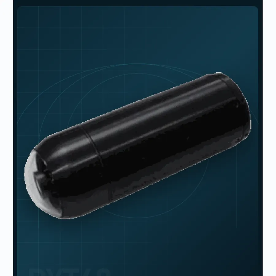
Visible-light missile seekerPrecision seekers
DYT40
A 200 g optical seeker for guided munitions.
≤200 gMass
2 km vehicleRange
≥100 gLaunch
Precision seekers
Seeker selection is driven by the munition envelope, target signature, terminal trajectory and the environmental conditions at the end of the flight.
Selection criteria
Use the same requirement boundary for every candidate, then compare documented evidence rather than headline numbers.
Confirm diameter, mass, centre of gravity, swept volume and shock environment before comparing optics.
Choose visible, thermal or dual-sensor imaging against the expected target and background contrast.
Review field of view, tracking method, acquisition logic, interface and behaviour through occlusion.
Supplier evaluation
Confirm envelope, mass, shock environment, sensor mix and terminal-control behaviour before comparing optics or headline detection figures.
Product family
Open a model page for supplier-stated specifications and integration notes.
A 200 g optical seeker for guided munitions.
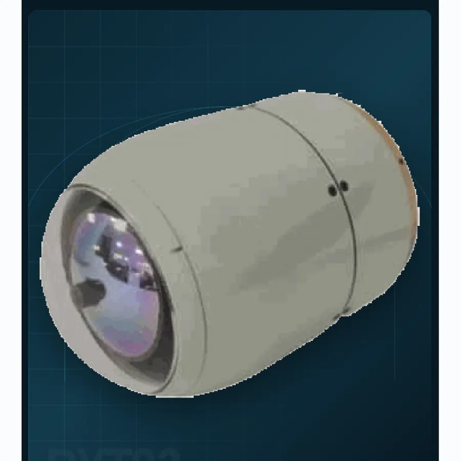
Infrared guidance for Mach 2 air-defence intercept.
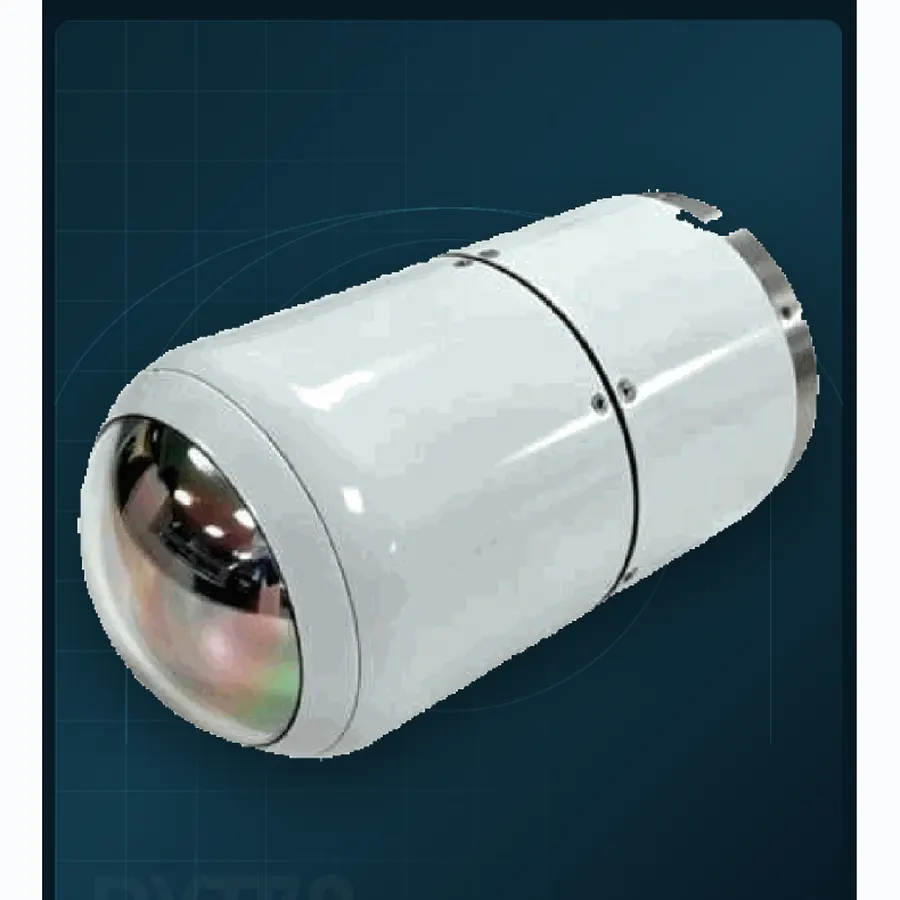
A compact IR / TV seeker for 78 mm envelopes.
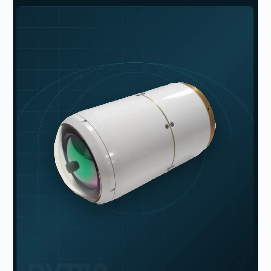
Dual-sensor guidance in a 680 g seeker.
Technical reading
Use the engineering guide to normalize claims across optics, stabilization, installed mass, power and interfaces before issuing a technical RFQ.
Engineering brief
Diameter, mass, shock, field of view and tracking behaviour are coupled. A seeker cannot be chosen from an optical table alone.
01 Engineering brief
A precision seeker lives inside a munition whose diameter, length, mass budget and launch environment are already fixed. The optical aperture, detector, stabilization mechanism and electronics must fit that envelope without compromising the airframe or the warhead. This is why a seeker datasheet cannot be read like a camera datasheet. A 40 mm seeker and a 93 mm seeker may both track a vehicle, but they do not serve the same munition class or the same engagement geometry.
The first design conversation should establish the diameter, available length, mass allowance, centre of gravity, power source, data interface and launch shock. Then define the target set, acquisition range, field of view and tracking rate. Only after those constraints are visible can the optical configuration be optimized. Starting with the detector and forcing the munition to fit around it usually produces a heavier and less reliable design.
02 Engineering brief
The DYT40 is a 200 g visible-light seeker in a Ø40 × 120 mm envelope, built around a 25 mm fixed-focus 2 MP camera. It is aimed at compact guided munitions and short-range terminal homing where low mass and cost matter. Its visible channel needs adequate scene illumination or a target with useful contrast; it is not a night-vision seeker.
The DYT70 uses an uncooled infrared core in a Ø70 × 130 mm envelope and is intended for low-altitude air defence and high-speed intercept. Its 35 mm thermal lens and 640 × 512 detector support a 2 km UAV-class target statement, while the onboard 6 TOPS compute and 30°/s tracking rate address moving targets. The Mach 2 flight-speed statement is an integration constraint, not a guarantee that every airframe will achieve it.
DYT78 packages infrared and visible imaging into a Ø78 × 140 mm envelope for compact munitions that need day/night acquisition. DYT93 provides a larger dual-sensor format with a 45 mm thermal lens, a 36 mm visible lens and a two-axis seeker for anti-tank and ground-attack applications. The dual-sensor architecture supports target confirmation before impact, but it also adds mass, power and calibration work.
03 Engineering brief
Tracking rate and field of view must be considered together. A narrow field gives more pixels on a distant target but demands accurate initial cueing and a fast enough tracking loop to keep the target inside the frame. A wide field tolerates pointing error but may not resolve the target at long range. The seeker's slew limits, gimbal travel and processing latency determine how quickly it can recover after launch or a target manoeuvre.
Launch shock is a key qualification parameter. The published ≥100 g figure for DYT40 and DYT93 indicates the class of environment the design is intended to survive, but the actual shock profile, duration and axis matter. Ask for the qualification test configuration, mounting interface and any isolation assumptions. A seeker that passes a bench shock test may still fail when the harness and airframe resonance are included.
Thermal and visible channels need boresight stability across temperature and shock. If the two images drift apart, target confirmation becomes unreliable and the track may jump between channels. Ask how boresight is set, measured and maintained over the operating temperature range. Include a post-shock boresight check in the acceptance plan.
04 Engineering brief
The seeker must exchange more than video with the munition. Typical signals include power, initialization, mode selection, track state, line-of-sight rates and health status. The exact interface must be defined in an interface control document. Ask for connector types, voltage levels, protocol timing, message rates and the behaviour after a transient fault. If the seeker includes onboard recognition, define what target classes it reports and how the operator or autopilot can override a track.
Mechanical integration includes the mounting flange, optical window, sealing and centre of gravity. The window material and coating must pass the required band and survive the launch environment. A window that is optically correct but insufficiently robust will fail at the worst moment. Confirm the cleaning, inspection and replacement procedure, and make sure the munition assembly process does not contaminate the optical surface.
For a dual-sensor seeker, define which channel owns the track and how the system transitions between them. A visible channel may provide better detail in daylight, while thermal imaging may be more reliable against a low-contrast background. The handoff logic should be documented and testable, not left as an operator preference.
05 Engineering brief
Request the environmental qualification plan, shock and vibration test reports, thermal cycling data, boresight measurements and optical performance at the temperature extremes. If the programme requires a specific standard, state it at the start; do not assume that a commercial test suite will satisfy a defence qualification authority. The test configuration should match the intended mounting and harness as closely as possible.
A guided-munition programme also needs configuration control. Firmware, detector lot, optical coating and mechanical revision can all affect behaviour. Ask how units are serialized, how changes are notified and what evidence accompanies each delivery lot. A seeker is not a commodity camera; traceability is part of the product.
The engineering inquiry should include the munition envelope, target set, launch environment and required interface. If the programme is early, a feasibility review can identify whether a documented format is close enough or whether a project-specific configuration is required. The guided-munitions application page shows how seekers fit into the wider mission chain.
Questions from integration teams
DYT40 is a compact visible-light seeker in a 40 mm envelope, while DYT70 is an infrared seeker in a 70 mm envelope aimed at air-defence and high-speed intercept. They differ in sensor band, mass, aperture and target environment, so they are not interchangeable.
Only if the interface is defined to be common and the programme confirms it. The two seekers have different envelopes and optical configurations. Treat the interface as a programme-specific item and request the current control document.
No. Onboard recognition can improve target selection and track continuity, but the munition's guidance loop, autopilot and safety logic remain responsible for flight. The seeker's track output and mode behaviour must be integrated and tested with the complete system.
An interface control document plus the current mechanical drawing and environmental qualification summary. These define whether the seeker can physically and electrically fit the munition before optical performance is discussed in detail.
Product directory
Every category page links to the full model range, application notes and the current evidence package.
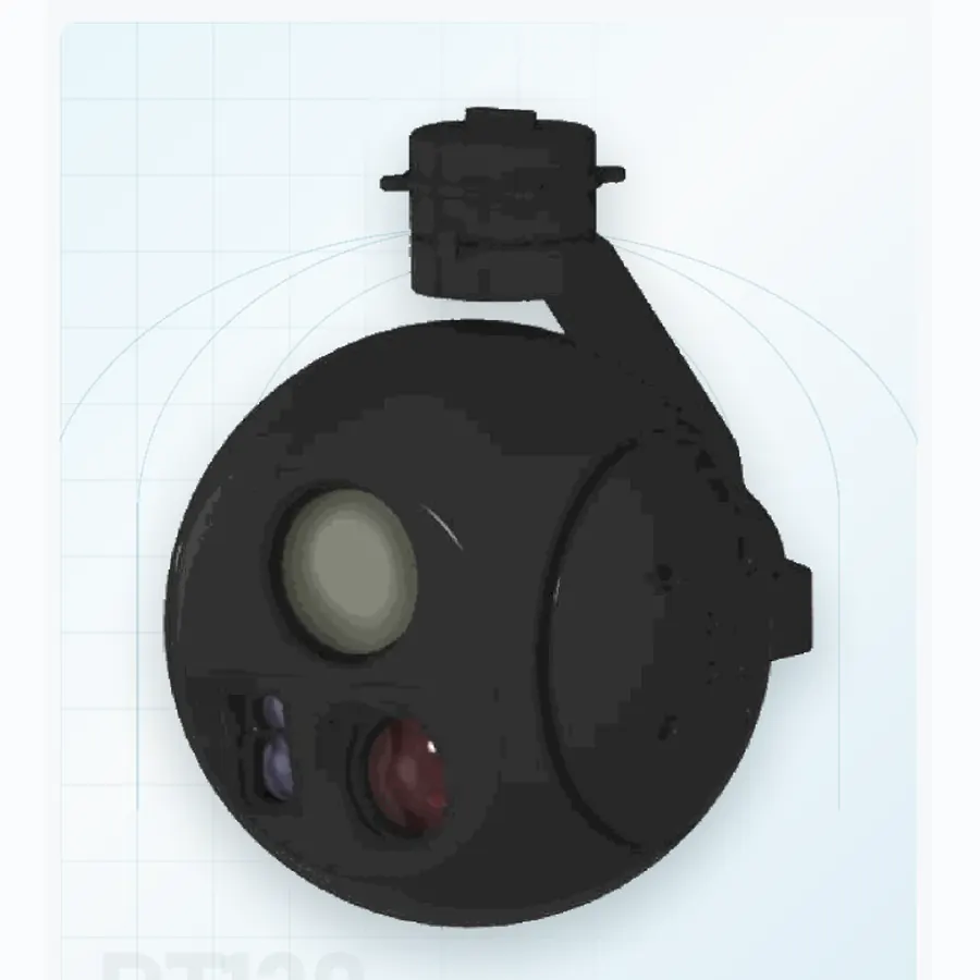 06 systemsAirborne payloadsSix stabilized pods from 190 g to 1.1 kg. Use visible, thermal and laser channels according to aircraft mass, endurance and recognition range.
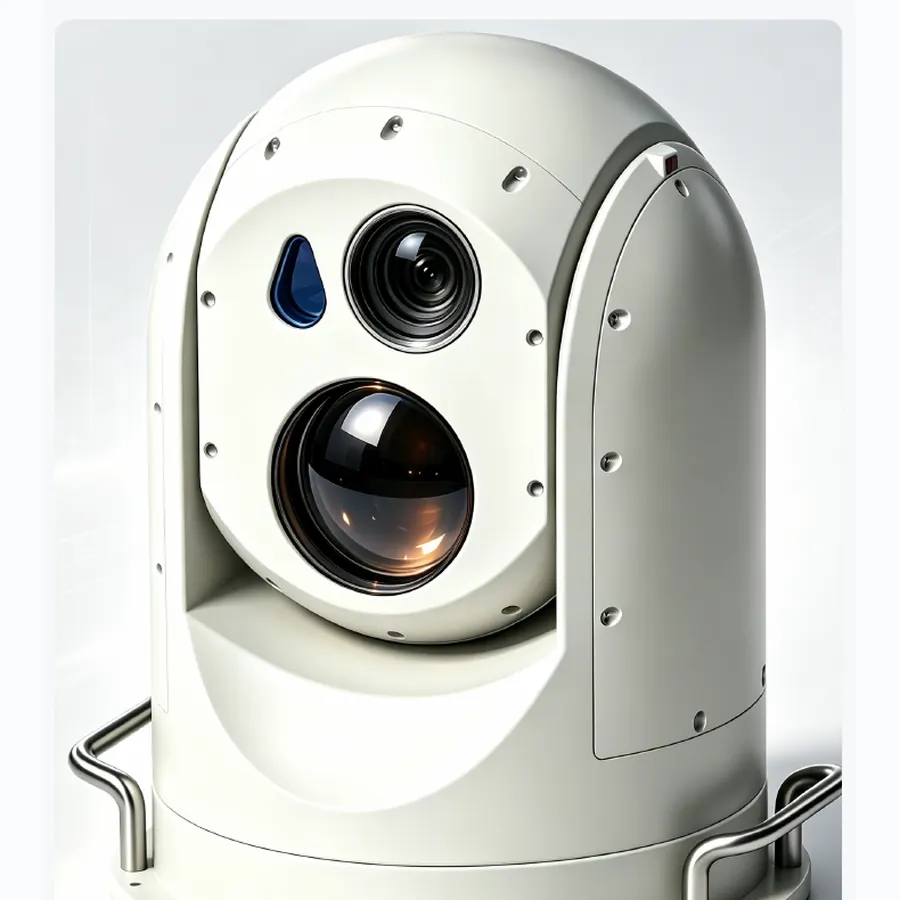 02 systemsEO/IR turretsTwo fixed-site turrets for persistent 60× optical and 75 mm thermal watch, with mount and sector coverage matched to the site.
04 systemsPrecision seekersFour documented envelopes from Ø40 to Ø93 mm for terminal homing, target confirmation and guided-munition integration.
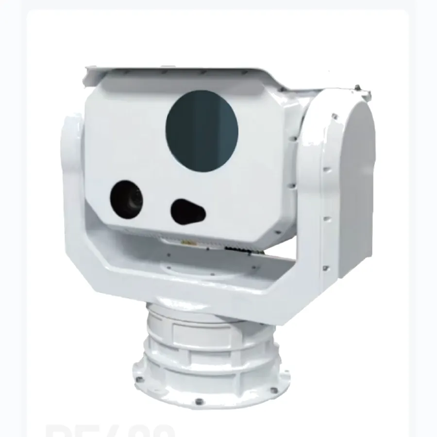 01 systemsCounter-UASOne 360° pedestal configured for rapid search, track acquisition and a clean handoff to an interceptor or effect layer.
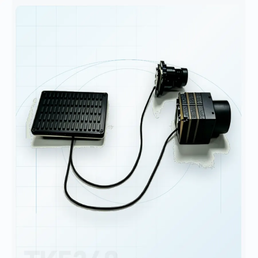 01 systemsAI coreAn onboard processing module for target recognition and track continuity when live video must be interpreted at the edge.
OEM and programme support
Share the platform, target set, range and interface constraints. We will map the relevant format and current documentation.