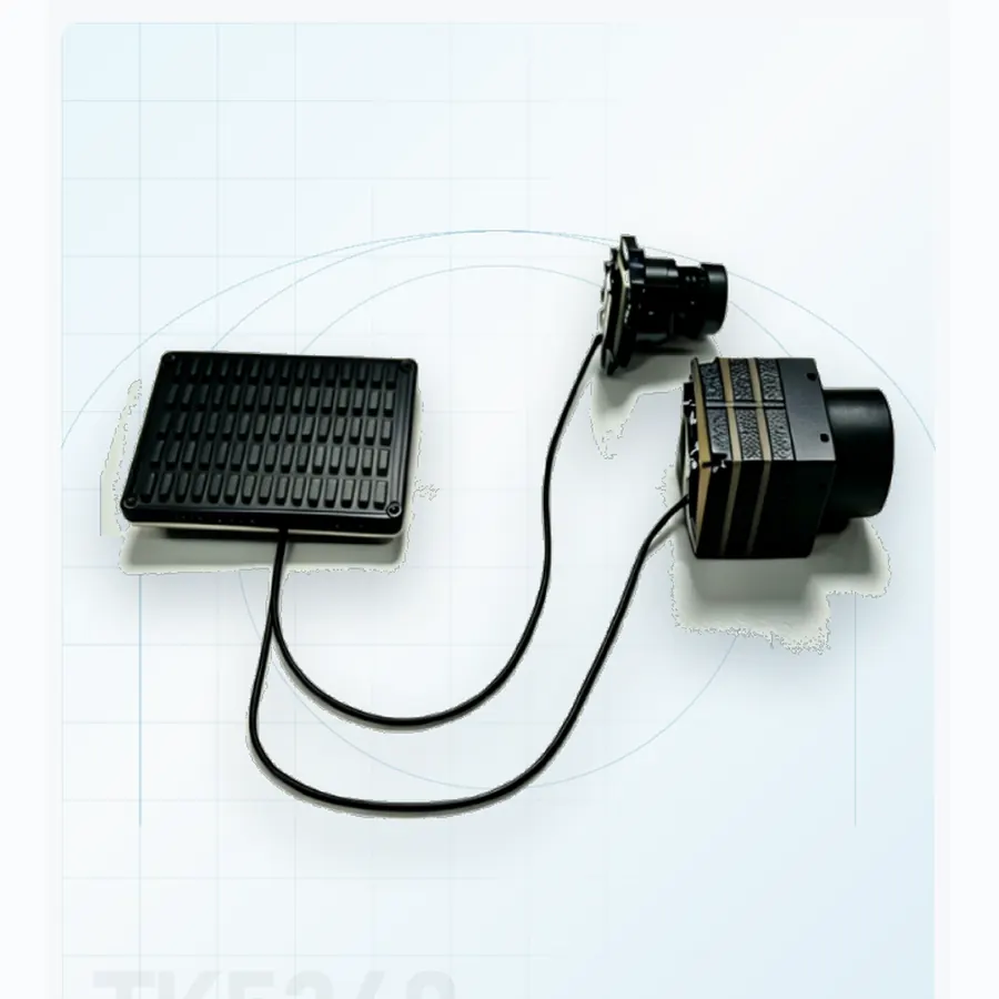
AI tracking module for UAVAI core
TK5340
Low-latency recognition for FPV and industrial UAVs.
6 TOPSAI compute
≤ 35 msLatency
53×40×10Board size
AI core
An onboard AI tracking module turns visible and infrared video into target tracks at the edge. Selection starts with the video pipeline, latency, power and the interface returned to the autopilot or payload.
Selection criteria
Use the same requirement boundary for every candidate, then compare documented evidence rather than headline numbers.
Match visible and thermal inputs, resolution, frame rate and synchronization to the sensors already on the platform.
Measure capture-to-track latency through the complete chain, not only the neural-network inference time.
Confirm board envelope, supply range, connector set, control protocol and track output for the airframe or payload.
Supplier evaluation
Compare compute, measured end-to-end latency, video inputs, target classes, power range and the tracking interface before requesting a quotation. Ask for recorded evidence on representative footage rather than a benchmark alone.
Product family
Open a model page for supplier-stated specifications and integration notes.
Technical reading
Use the engineering guide to normalize claims across optics, stabilization, installed mass, power and interfaces before issuing a technical RFQ.
Engineering brief
Compute, video pipeline, latency and interface decide whether an edge AI module is useful inside a UAV payload.
01 Engineering brief
An onboard AI tracking module processes live video inside the aircraft or payload instead of sending every frame to a ground station. Its job is to turn pixels into a usable track: select a target, keep it in the frame, report its position and hand the track to a payload controller, autopilot or operator display. That sounds like a software function, but the product is a hardware module with camera inputs, compute, memory, power conversion and an interface. All of those parts affect whether the track arrives in time to be useful.
The distinction between detection and tracking matters in procurement. Detection finds candidate objects in a frame. Tracking maintains identity and position across frames while the target, camera or aircraft moves. A module that draws boxes on a demonstration video may still fail when the target is partially occluded, the camera zooms, the airframe vibrates or two similar objects cross. The TK5340 onboard AI tracking module is documented for manual selection, automatic recognition, multi-target tracking and track continuity through occlusion, with target classes that include person, vehicle, boat and UAV. Those functions should be tested as a sequence, not as separate feature labels.
Edge processing also changes the system architecture. Keeping video on the aircraft can reduce downlink bandwidth and remove a round trip to the ground station. It can improve response time for an interceptor or a stabilized payload, and it can keep the track alive when the data link degrades. The trade-off is that the airframe must supply power, cooling and a reliable video path, and the module must expose a track interface that the flight controller or payload can actually use. A good AI module is therefore co-designed with the payload, not added after the optics are frozen.
02 Engineering brief
The TK5340 uses an RK3576 processor with a 6 TOPS neural processing unit. That figure describes the accelerator's peak capability, not the frame rate or accuracy a mission will see. Real performance depends on input resolution, model size, number of targets, pre-processing, post-processing and the tracking algorithm that runs alongside the detector. A six-TOPS module can be fast enough for a compact UAV payload, but the supplier should show measured results on representative footage rather than a synthetic benchmark.
An AI object tracking pipeline usually has four stages: capture, pre-process, detect or classify, and associate the result with an existing track. The association step is where multi-target behaviour becomes visible. If two targets cross, the module must decide which detection belongs to which track. If a target disappears behind a mast, the tracker must either coast on its last motion estimate or declare a loss according to a defined rule. Ask how the module behaves in each case and whether the behaviour is configurable for the mission.
Target classes are also a procurement decision. A general-purpose person/vehicle model may not recognise a small boat against a bright sea surface, and a UAV at long range may occupy very few pixels. The documented classes for TK5340 are person, vehicle, boat and UAV, but the operating envelope for each class must be confirmed with matched imagery. If the programme needs a new class or a customer-specific classifier, ask whether the module supports model updates, how those updates are validated and what happens to the existing track when a model changes.
The edge AI tracking module also needs a defined output. A bounding box in image coordinates is enough for a display but not for pointing a gimbal. A track reported in payload angles, geographic coordinates or body-frame rates requires calibration, time alignment and a coordinate transform. Define the output the downstream system needs before comparing compute specifications. The interface, not the TOPS number, often determines whether integration succeeds.
03 Engineering brief
TK5340 provides two MIPI visible inputs and one DVP infrared input, with documented visible lens options of 8, 16, 25 and 35 mm and infrared options of 9.1, 19, 25 and 35 mm. The lens choice belongs to the camera or payload design, not to the AI module alone. A wide lens helps search and keeps a manoeuvring target in view; a narrow lens puts more pixels on a distant object but makes initial acquisition harder. The module must work with the field of view and frame rate that the mission actually uses.
When visible and thermal video are both present, synchronization becomes a real engineering task. The two channels may have different exposure times, frame rates, latencies and aspect ratios. If their timestamps are not aligned, a track that looks correct on the thermal image can be displaced on the visible image, or a handoff between channels can jump. Ask how frames are timestamped, whether the module exposes a common clock, and how the two inputs are calibrated to a common optical axis. A mechanical boresight is only the start; software alignment and time alignment must also be verified.
The video path should be tested with the actual camera modules and cable lengths. MIPI interfaces are sensitive to signal integrity, connector quality and electromagnetic interference. A bench demonstration with short cables may not represent an aircraft installation with a long harness, a hot enclosure and multiple transmitters nearby. Request an integration drawing, a cable specification and a test procedure that covers the installed configuration. The airborne payload category shows the camera formats that the module may need to support; the thermal camera range covers the infrared side in more detail.
04 Engineering brief
TK5340 is documented with a tracking latency of ≤35 ms. That number is only useful if the supplier defines where the clock starts and stops. Is it sensor exposure to track output, video-frame arrival to output, or neural-network inference alone? A 35 ms inference result plus a 30 ms camera pipeline plus a 20 ms control loop is a very different system from a 35 ms end-to-end claim. Ask for the measurement setup, the frame rate and the output interface used in the test.
The module accepts 12–60 V and is described for 6S and 12S packs, which covers a useful range of UAV power systems. The input range does not remove the need to check transient behaviour, reverse polarity, inrush current and heat. The board envelope is documented as 53 × 40 × 10 mm, so the mechanical design must provide mounting, connector clearance and a thermal path. A compact board in a sealed payload enclosure can run hotter than a bench test suggests, and sustained high frame-rate inference may reduce the achievable clock or require a thermal design change.
Power and mass budgets should include the camera modules, harness, cooling and any interface board. The AI module is only one line in the budget. If the payload already has a stabilized gimbal, the added processing may be modest compared with the mechanics; if the module is added to a small FPV airframe, every gram and every watt matters. Compare the complete processing chain, not just the module datasheet. The TK5340 product page lists the supplier-stated electrical and mechanical figures, and the current drawing should be requested for the programme.
05 Engineering brief
An onboard AI tracking module supplier should be able to provide more than a feature list. Request recorded clips that show the intended target classes at the intended range, in the intended lighting and background. For a UAV target, include sky, terrain and clutter backgrounds; for a boat, include sun glint and wave motion; for a person, include partial occlusion and groups. Ask for the original frame rate and resolution, not a compressed marketing video. A short clip can hide exactly the failure modes that matter in service.
Define the tracking metrics in advance. Useful measures include acquisition time after a cue, track continuity through occlusion, identity switches in a multi-target scene, false tracks per minute and jitter at the output. If the mission needs a track through a zoom change, test the zoom. If it needs a track during aircraft manoeuvre, test with representative vibration or motion. The 6 TOPS compute figure and the ≤35 ms latency statement should be tied to these measurements rather than reported in isolation.
Ask for the interface control document, connector list, pinout, protocol timing, video formats and the definition of the track message. Confirm whether the module outputs a bounding box, a target angle, a body rate, a geographic coordinate or a combination, and how the coordinate frame is defined. If the module is paired with a gimbal, confirm who closes the stabilization loop and how the track is handed to the gimbal controller. A track that is accurate on screen but expressed in the wrong frame can steer the payload away from the target.
For a counter-UAS or interceptor application, the evidence package should include cue-to-track time and behaviour when the target is lost. The counter-UAS category explains how the optical layer hands off to a response layer, while the applications section maps the wider mission chain. For an ISR payload, the evidence should include recording, metadata and operator display behaviour. The same module can serve both, but the acceptance tests are not identical.
06 Engineering brief
An OEM payload programme should settle five interface questions early: how video enters the module, how the track leaves it, how the module is powered, how it is cooled and how firmware is updated. The answers determine the harness, the enclosure, the connector strategy and the qualification plan. If the module is mounted on a gimbal, the rotating interface and cable wrap must be included in the design. If it is mounted in the airframe, the distance to the cameras and the electromagnetic environment become the dominant risks.
Configuration control is part of the product. Ask for the firmware version, model version and any customer-specific parameters, and define how changes are notified. A model update can change the target classes, the confidence threshold or the track behaviour. The programme should have a regression test set that runs after every update. If the customer supplies its own model, clarify who owns the training data, who validates the output and how the model is protected in the delivered hardware.
Environmental qualification should match the installation. A board that is qualified on a bench may still fail under vibration, thermal cycling or humidity in a sealed payload. Ask for the operating and storage temperature range, shock and vibration evidence, conformal coating and connector retention. For a defence programme, also ask about traceability, export classification and long-term availability. These questions are easier to answer before the design is frozen than after the first flight.
The engineering team can review the camera interfaces, target set, latency budget and track output against the documented module. A short review is usually enough to decide whether TK5340 is a direct fit, whether a carrier board is needed, or whether the programme should start with a project-specific configuration. The goal is not to buy the highest compute figure; it is to deliver a track that the payload can use reliably in the installed environment.
Questions from integration teams
Detection finds candidate objects in a frame. Tracking maintains a target's identity and position across frames while the scene changes. A useful module must do both and report a stable track, not just draw a box on one image.
The module is documented with two MIPI visible inputs and one DVP infrared input. Simultaneous operation, frame rate and synchronization depend on the camera configuration and must be confirmed with the actual sensors and harness.
The supplier states ≤35 ms tracking latency, but the measurement boundary must be confirmed. Ask whether it covers exposure, video transport, inference and output, and test the complete chain in the installed payload.
Lens options, carrier board, connectors, firmware and track output can be discussed as programme-specific items. The current module should be evaluated first against the camera interface, power, envelope and latency budget before a custom variant is proposed.
Onboard processing reduces downlink dependence and can shorten the response loop, but it adds power, heat and integration work to the aircraft. The right choice depends on the mission's latency, bandwidth and survivability requirements.
Product directory
Every category page links to the full model range, application notes and the current evidence package.
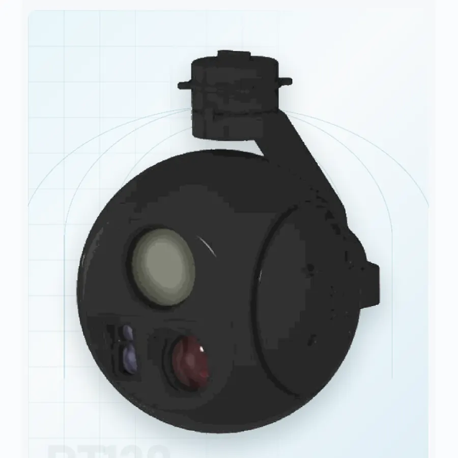 06 systemsAirborne payloadsSix stabilized pods from 190 g to 1.1 kg. Use visible, thermal and laser channels according to aircraft mass, endurance and recognition range.
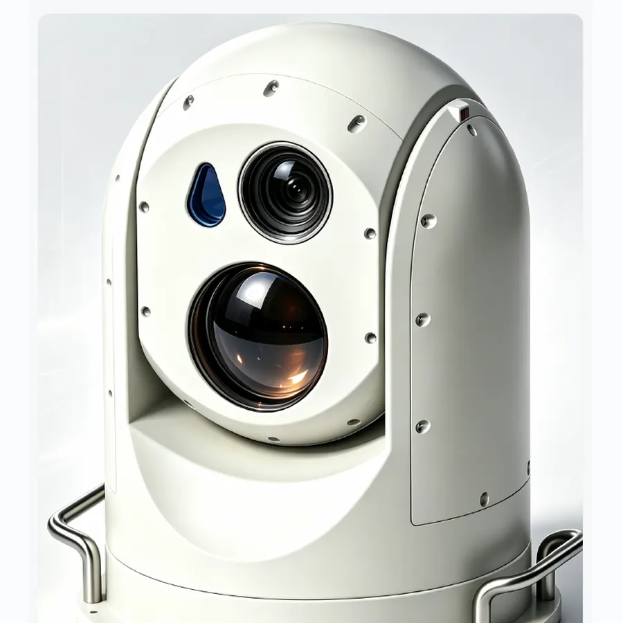 02 systemsEO/IR turretsTwo fixed-site turrets for persistent 60× optical and 75 mm thermal watch, with mount and sector coverage matched to the site.
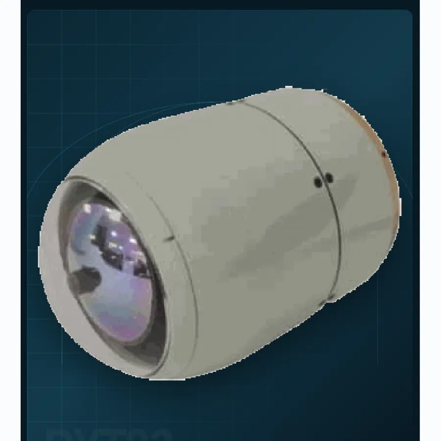 04 systemsPrecision seekersFour documented envelopes from Ø40 to Ø93 mm for terminal homing, target confirmation and guided-munition integration.
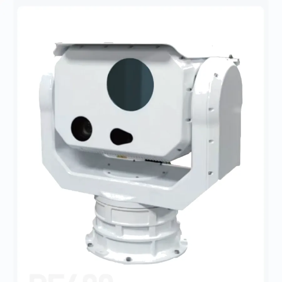 01 systemsCounter-UASOne 360° pedestal configured for rapid search, track acquisition and a clean handoff to an interceptor or effect layer.
01 systemsAI coreAn onboard processing module for target recognition and track continuity when live video must be interpreted at the edge.
OEM and programme support
Share the platform, target set, range and interface constraints. We will map the relevant format and current documentation.