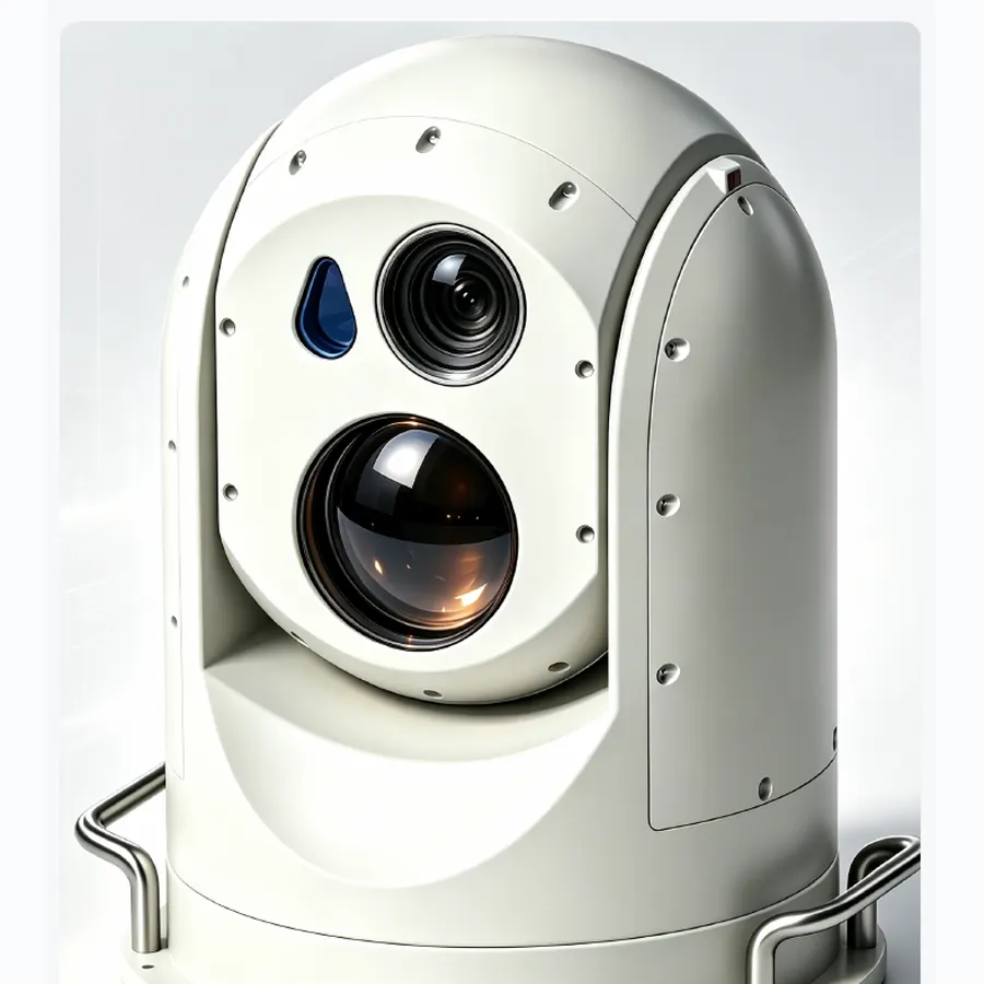
60× EO/IR surveillance turretEO/IR turrets
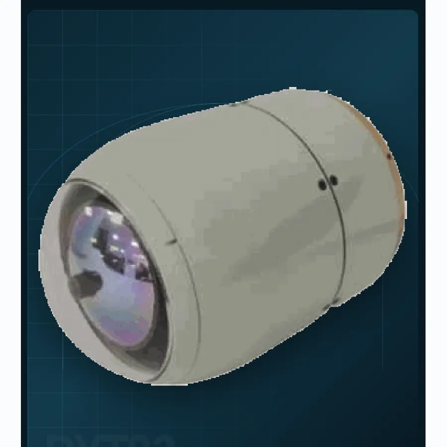
PD230
A 60× optical turret with a 75 mm thermal channel.
60× opticalZoom
75 mmThermal
20 kgWeight
EO/IR turrets
Fixed-site turrets trade payload mass for long focal length, stable pointing and continuous observation. The selection starts with the sector, target and recognition requirement.
Selection criteria
Use the same requirement boundary for every candidate, then compare documented evidence rather than headline numbers.
Define the required azimuth and elevation sector, revisit time and whether continuous 360° coverage is mandatory.
Combine visible zoom, thermal focal length and atmospheric conditions to estimate usable identification range.
Review pedestal load, power, network, control room and environmental protection with the fixed-site design.
Supplier evaluation
Compare coverage, recognition range, pedestal load, power, network interfaces and environmental protection before requesting a site-specific quotation.
Product family
Open a model page for supplier-stated specifications and integration notes.
A 60× optical turret with a 75 mm thermal channel.
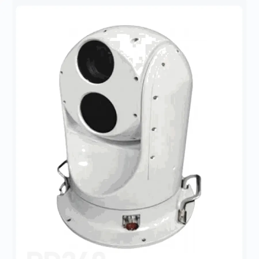
60× optical reach for wide-area surveillance.
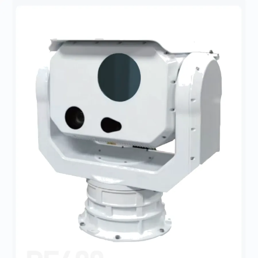
A fixed-site counter-UAV eye with a 3-second panoramic scan.
Technical reading
Use the engineering guide to normalize claims across optics, stabilization, installed mass, power and interfaces before issuing a technical RFQ.
Engineering brief
Fixed-site EO/IR turrets are selected by sector coverage, recognition distance, pedestal load and the control-room workflow behind them.
01 Engineering brief
An EO/IR surveillance turret is part of a site, not a standalone camera. The first design question is which airspace or ground sector must be covered, at what revisit rate, and from which elevation. A continuous 360° requirement produces a different pedestal, slip-ring and control architecture from a sector scan that sweeps backwards and forwards. The second question is what the operator must be able to decide at the end of the optical chain: detect movement, recognise a vehicle type, identify a person or measure a target location.
These questions determine whether a 60× visible zoom and a 75 mm thermal channel are enough, or whether the site needs multiple turrets with overlapping coverage. A single long-range sensor cannot simultaneously provide high revisit rate over a wide sector and a narrow, stable image at maximum zoom. The honest design process accepts that trade and allocates sensors accordingly.
02 Engineering brief
The PD230 and PD240 share a 20 kg two-axis architecture, a 2560 × 1440 visible sensor with 60× zoom and a 640 × 512 thermal imager with a 75 mm lens. Their published visible detection figures are also similar. The important differences are in the mechanical and pointing envelope, and in the thermal detection figure: PD240 lists a 1.5 km IR UAV detection range, while PD230 lists 3 km. Those differences should be checked against the current supplier datasheet and the intended installation.
PD240's pitch range of −75° to 0° suits a downward-looking site where the primary task is ground or low-altitude surveillance. PD230's published envelope extends upward, which may matter for airspace monitoring. Neither specification alone tells you which turret will see a small target against a cluttered background. The site elevation, background temperature and atmospheric path are part of the result.
The PF400 is a different instrument: a counter-UAS turret with a fast steering mirror, 360° continuous slew and a 5 km laser rangefinder. It is optimized for rapid panoramic search and lock-on rather than the slower, continuous observation typical of a surveillance pedestal. Mixing the two roles in one procurement without defining them can lead to a system that is mediocre at both.
03 Engineering brief
Published detection ranges are usually based on a target of a stated size, a defined contrast and a clear atmosphere. Recognition and identification require more pixels on target and therefore shorter usable distances. The calculation should start with the sensor's angular resolution, the target dimension and the number of pixels needed for the task. Then apply an allowance for atmospheric attenuation, platform vibration and display quality.
For visible imaging, zoom is not the same as resolution. A 60× zoom lens on a 1440-line sensor may produce a highly magnified but soft image if the optics, focus and atmospheric path cannot support the magnification. For thermal imaging, the 75 mm lens and detector pitch determine the instantaneous field of view; a larger detector or a longer lens can improve pixel coverage but narrows the search field. Always ask for a matched image at the claimed distance, not only a range table.
Target location adds a laser rangefinder and a boresight requirement. The rangefinder's beam divergence, update rate and minimum range must match the target geometry. A 5 km range figure is not useful if the beam is too wide to isolate a small object or if the range is not aligned with the imaging channel. Check the boresight procedure and the stability of alignment after transport.
04 Engineering brief
A 20 kg payload produces static and dynamic loads that the mast, foundation or roof mount must carry. Obtain the centre of gravity, wind-load assumptions and the torque produced during acceleration and braking. Check cable routing through the azimuth axis and confirm whether a slip ring is required for continuous rotation. If the turret is mounted on a vehicle or a temporary mast, the vibration and sway environment changes the stabilization problem.
Power planning should separate average and peak consumption, including heaters, window defogging and panic/slew modes. Confirm the supply voltage, connector type, surge protection and earthing arrangement. For network integration, ask for the video and control protocols, the number of simultaneous streams, the metadata format and the behaviour after a network interruption. A control-room system may need ONVIF or a vendor SDK; confirm which is available before assuming plug-and-play compatibility.
Environmental protection must be matched to the site. IP66 is a useful baseline for rain and dust, but coastal installations may need corrosion protection and regular window cleaning. Ask about operating temperature, humidity, salt fog and the maintenance interval for wipers or heaters. A turret that is optically excellent but inaccessible for service will not provide persistent surveillance.
05 Engineering brief
Commissioning should begin with a mechanical and electrical check before the turret is pointed at a live scene. Verify the mount torque, cable clearance, supply voltage and network path. Then run a slow 360° sweep and a series of commanded moves through the full elevation range. Record settling time, overshoot and any cable or housing interference.
Next, perform an optical alignment check at wide and narrow zoom. Confirm that the visible and thermal channels remain boresighted across the zoom range and that the laser rangefinder agrees with a known distance. Capture reference frames at several zoom settings and ambient conditions. Finally, test the operator workflow: can the control room find, identify and hand off a target without losing the track? The technical acceptance criteria and the operational workflow should be signed off together.
Keep a commissioning record that includes firmware versions, network settings, alignment results and baseline images. This becomes the reference for future maintenance and for comparing a second site. The engineering team can review the site plan, power and data requirements before a quotation is finalized.
Questions from integration teams
They share the same visible and thermal optical class and a 20 kg two-axis format, but their pointing envelopes and published thermal detection figures differ. PD230 lists upward elevation and a longer IR UAV detection figure; PD240 lists a downward-looking pitch range. Confirm the latest supplier data against the intended site before choosing.
Only if the mission requires identification at long range. High zoom narrows the field of view and magnifies residual motion and atmospheric distortion. Many sites benefit from a wider search channel plus a narrow confirmation channel, or from multiple turrets with overlapping coverage.
The mechanical and stabilization assumptions change on a moving platform. A pedestal designed for a fixed mast may not have the control bandwidth or shock isolation for vehicle use. Discuss the vibration profile and mounting design before assuming a fixed-site turret can be repurposed.
Mechanical travel, cable clearance, power quality, network recovery, visible/thermal boresight, laser alignment, image quality at representative zoom and the full operator handoff workflow. Record the results and baseline imagery so future maintenance can be compared against a known state.
Product directory
Every category page links to the full model range, application notes and the current evidence package.
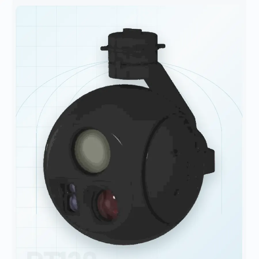 06 systemsAirborne payloadsSix stabilized pods from 190 g to 1.1 kg. Use visible, thermal and laser channels according to aircraft mass, endurance and recognition range.
02 systemsEO/IR turretsTwo fixed-site turrets for persistent 60× optical and 75 mm thermal watch, with mount and sector coverage matched to the site.
 04 systemsPrecision seekersFour documented envelopes from Ø40 to Ø93 mm for terminal homing, target confirmation and guided-munition integration.
01 systemsCounter-UASOne 360° pedestal configured for rapid search, track acquisition and a clean handoff to an interceptor or effect layer.
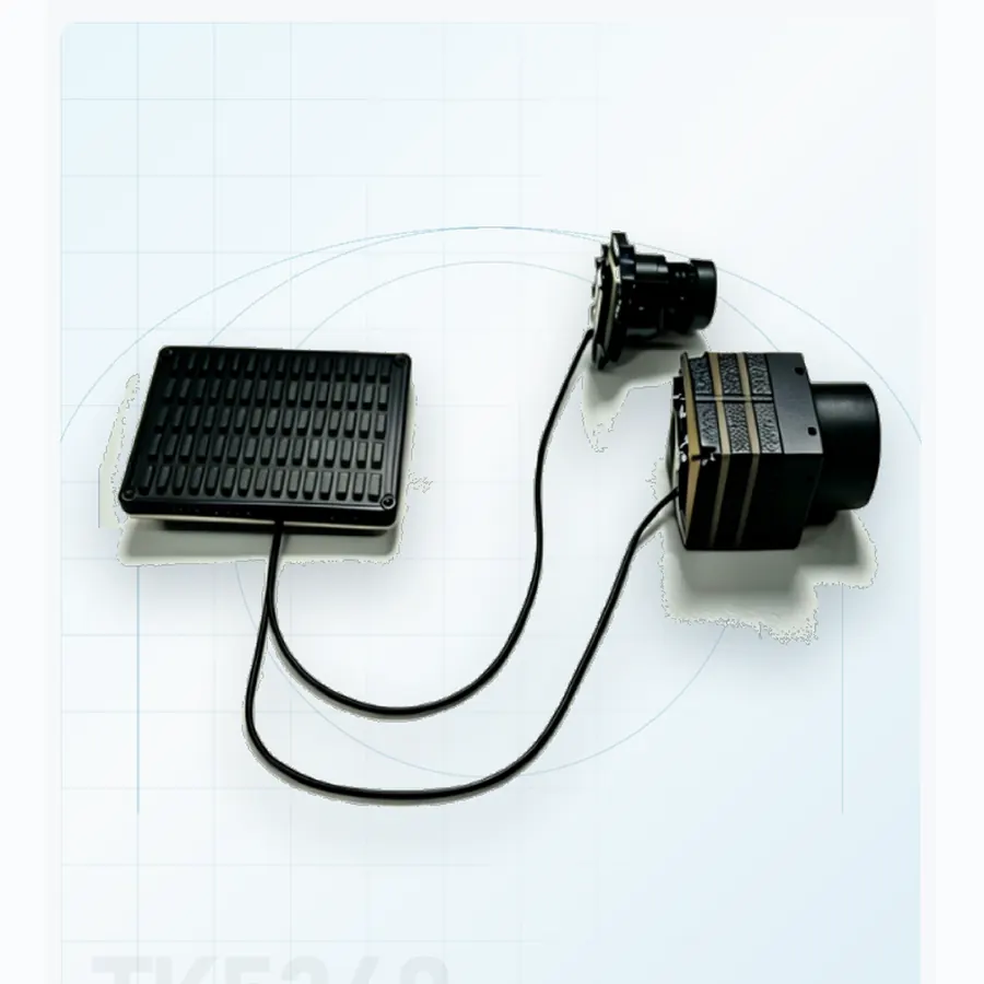 01 systemsAI coreAn onboard processing module for target recognition and track continuity when live video must be interpreted at the edge.
OEM and programme support
Share the platform, target set, range and interface constraints. We will map the relevant format and current documentation.