FPV counter-UAV gimbal cameraAirborne payloads
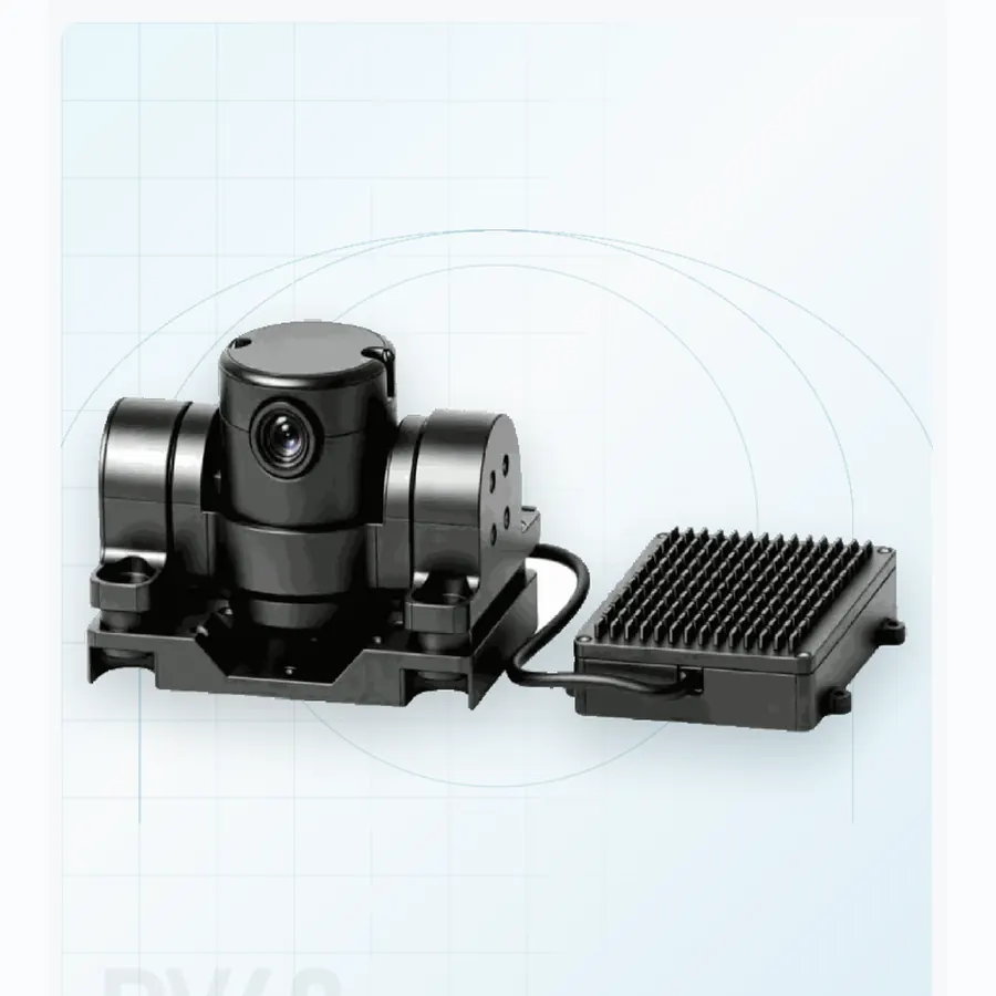
PV40
A 190 g stabilized eye for FPV interceptors.
≤190 gMass
0.5 km personDetection
2-axisAxes
Airborne payloads
Select a stabilized airborne payload around platform mass, target detail, endurance and the number of sensing channels that must share one line of sight.
Selection criteria
Use the same requirement boundary for every candidate, then compare documented evidence rather than headline numbers.
Compare complete installed mass, swept envelope, startup current and continuous power against the airframe allowance.
Match detector, lens and field of view to the smallest feature that must be recognized at the working distance.
Confirm mount pattern, connector set, control protocol, video stream and behaviour after link loss.
Supplier evaluation
Compare installed mass, optics, power and interfaces across the six configurations, then request current data sheets and a quotation for the shortlisted format.
Product family
Open a model page for supplier-stated specifications and integration notes.
A 190 g stabilized eye for FPV interceptors.
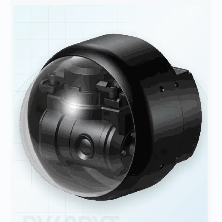
Stabilized vision at 200 m/s.
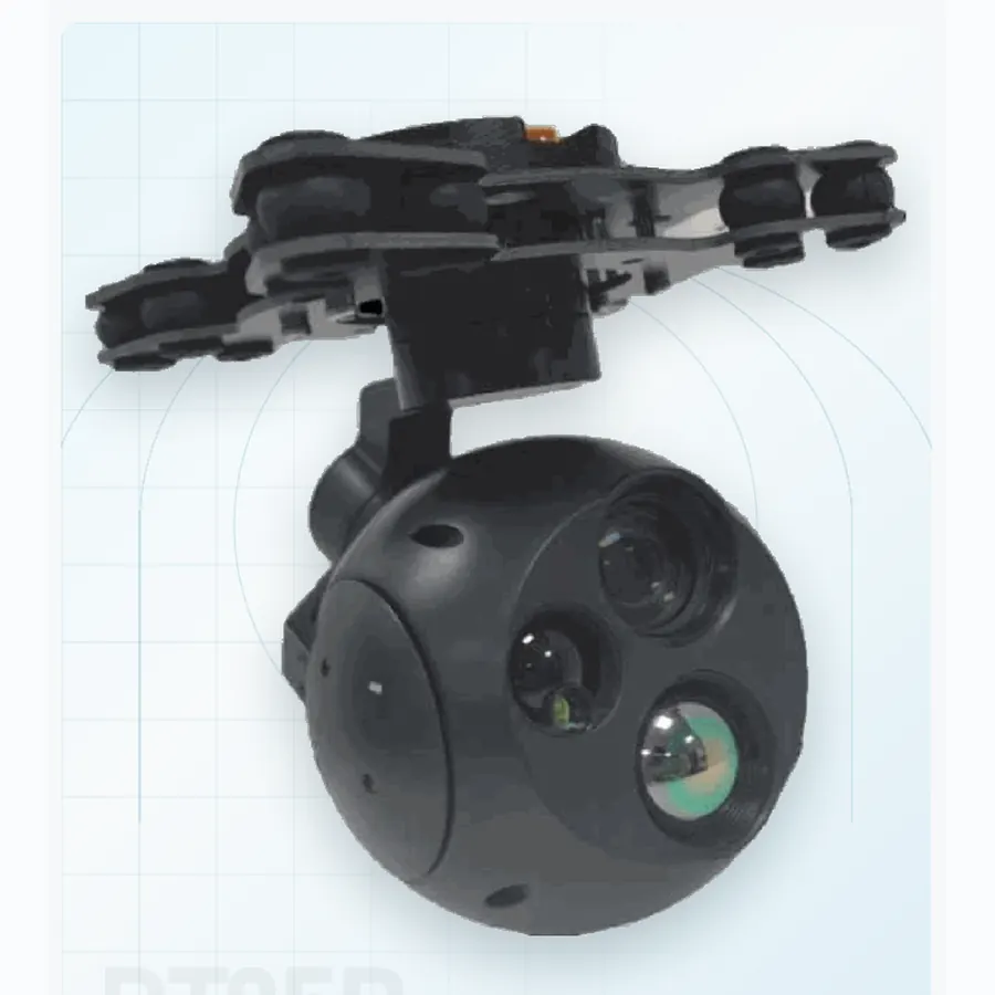
4K daylight, thermal vision and 1.5 km ranging.
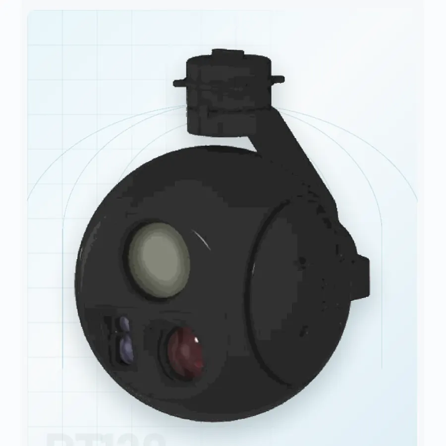
30× zoom, thermal imaging and 2 km ranging.
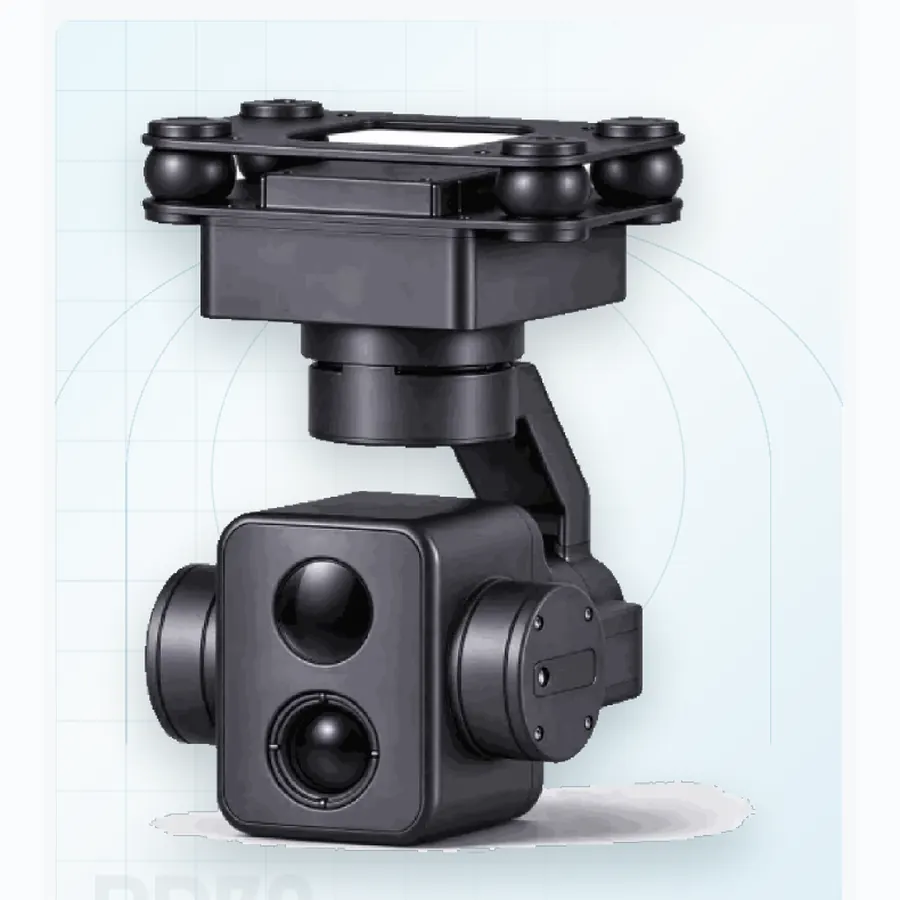
A 250 g three-axis gimbal with thermal and 4K.
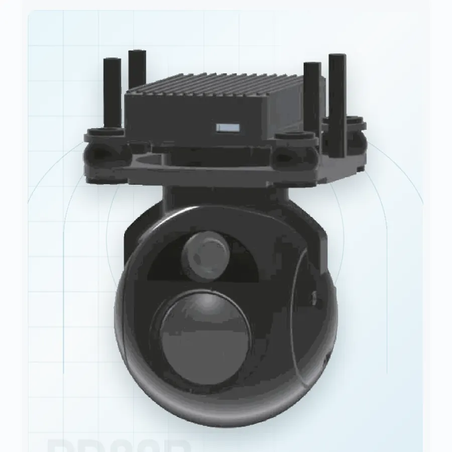
A 285 g terminal tracker for loitering munitions.
Technical reading
Use the engineering guide to normalize claims across optics, stabilization, installed mass, power and interfaces before issuing a technical RFQ.
Engineering brief
A practical way to separate airframe limits, optical reach and stabilization claims before shortlisting a payload.
01 Engineering brief
A UAV gimbal camera is not selected from a catalogue in isolation. It becomes part of an aircraft whose endurance, centre of gravity, vibration environment and data link are already constrained. The productive sequence is therefore to fix the platform allowance first, then define the image that the mission must deliver, and only then compare optical and stabilization configurations. A payload that looks impressive on a specification sheet can still be the wrong choice if its installed mass, swept volume or startup current falls outside the airframe envelope.
Begin with four numbers: maximum payload mass with the isolation mount and harness, available electrical power at peak and continuous load, the volume swept by the gimbal through its full travel, and the data rate the link can sustain without affecting flight control. These are integration limits, not marketing preferences. Once they are written down, the six airborne formats in this range can be assessed on a common basis instead of by headline zoom or detector resolution alone.
02 Engineering brief
The PV40 is a visible-light micro pod intended for FPV interceptors and other very small airframes. Its two-axis stabilization, 190 g class mass and 16 mm lens prioritise response and low payload penalty. The PV40DYT keeps a similar visible-light core but adapts the enclosure and control envelope for high-speed rocket airframes, including a 200 m/s flight-speed statement. Neither should be treated as a general-purpose ISR turret.
The PD70 moves into a 250 g three-axis class while adding a 640 × 512 thermal channel and a 4K visible sensor. It is a natural starting point for small UAVs that need day and night awareness without a large payload bay. The PD80B has a different purpose: its 25 mm thermal optic and wide visible camera are arranged for terminal tracking from a loitering munition, where the target is close and the airframe may not return.
At the upper end, PT95B combines 4K visible imaging, thermal vision and a 1.5 km laser rangefinder in a 700 g three-axis pod. PT130 extends optical reach with a 30× visible zoom, a 25 or 35 mm thermal lens and a 2 km rangefinder in a 1.1 kg package. The choice between them is usually a trade between endurance and the smallest target detail that must be recognised at the working distance.
03 Engineering brief
Field of view, focal length, detector format and display magnification must be evaluated together. A 4K sensor does not guarantee more usable detail if the lens projects a wide scene onto a small portion of the array. Conversely, a lower-resolution sensor with a longer lens can put more pixels on a distant vehicle. The useful calculation is pixels across the target at the expected slant range, followed by an honest allowance for atmospheric contrast, platform motion and the operator's display.
Thermal selection adds another layer. Detector resolution, pixel pitch, lens focal length and thermal contrast determine whether a person or vehicle separates from the background. A narrow thermal field of view improves pixel coverage but makes it harder to find a target that is not already cued. Wide-area search and long-range identification therefore pull in opposite directions. Tri-sensor payloads solve part of that problem by letting the operator search with a wider channel and confirm with a narrow one, but they also increase mass, power and calibration complexity.
Laser rangefinders should be specified with their measurement range, wavelength, beam divergence, update rate and eye-safety class. A single headline range does not describe performance against small, low-reflectivity targets or in poor visibility. Ask for the target reflectivity and atmospheric assumptions behind the number, and check whether the laser shares a boresight with the imaging channels. A range that is not aligned with the optical line of sight creates errors during target location.
04 Engineering brief
Two-axis and three-axis are architecture labels, not performance grades. What matters is the residual angular motion at the focal length the mission will actually use, the settling time after a commanded slew, and the ability to recover after a manoeuvre or temporary loss of track. A narrow zoom setting magnifies any residual motion, so a stabilization claim made at wide angle may tell the operator very little about the image at 30× zoom.
The airframe is part of the control problem. Motor vibration, propeller harmonics, hard mounts and flexible airframes can all inject disturbance that no gimbal can completely remove. The isolation mount, centre of gravity and cable service loop therefore belong in the same review as the gimbal controller. Request a vibration profile and a matched image sequence rather than a single still frame. For a compact explanation of the architectural trade, read the two-axis versus three-axis integration guide.
05 Engineering brief
Obtain a drawing that shows the complete installed envelope, including the damper, connectors and the space required for cable movement. Check the mounting pattern against the airframe hard points and confirm that the gimbal can reach its stated travel without striking the fuselage, landing gear or antenna. The centre of gravity should be checked in the stowed and deployed positions. A payload that balances on the bench may still change the aircraft's handling when it is extended into the airflow.
Power figures need the same discipline. Separate startup, steady-state, peak-slew and heater consumption where applicable. Confirm the input voltage range against the actual battery or converter, and check whether the airframe can supply inrush current without disturbing the flight controller. For data, identify the physical connector, video format, control protocol, update rate and expected behaviour after link loss. If the payload supports onboard tracking, define whether track coordinates, bounding boxes or compressed video cross the interface, and at what rate.
Do not accept “Ethernet” or “serial” as a complete interface answer. Ask for the connector pinout, protocol version, IP addressing assumptions, timestamp behaviour and the format of any metadata. These details determine whether integration takes days or months. The resource library is the place to request current drawings and interface information for the shortlisted model.
06 Engineering brief
A credible evaluation package should include matched visible and thermal frames at defined distances, a recorded stabilization sequence at representative zoom, power measurements at startup and continuous load, and a mechanical drawing with the installed envelope. If laser ranging is part of the requirement, ask for a range test against targets of stated size and reflectivity. If tracking is relevant, request a sequence that includes target occlusion, reacquisition and a second target entering the field.
Record the firmware revision, test date, mounting arrangement and environmental conditions with every item. That turns a demonstration into evidence that can be compared across suppliers. It also gives the integration team a baseline for acceptance testing after the payload is installed on the aircraft. A short bench test and a documented flight test are more useful than an unlabelled highlight video.
Finally, map the requirement to one primary format and one fallback. The primary choice should meet the mission with margin; the fallback should protect schedule if mass, power or delivery changes. The UAV gimbal camera specification guide provides a normalized comparison method, and the engineering inquiry form can be used to send the platform envelope for a configuration review.
Questions from integration teams
No. Three axes can correct an additional disturbance direction, but the right choice depends on aircraft motion, field of view, mass and mission duration. A well-integrated two-axis pod can be preferable when the airframe cannot afford the extra mass or volume. Compare residual image motion at the intended zoom, not the axis count alone.
Often only with a compromise. A zoom or multi-sensor payload can search wide and confirm narrow, but the wide channel may have less target detail and the narrow channel may be harder to point without cueing. Define the search field, the recognition distance and the time available before deciding whether one payload or a two-payload architecture is more efficient.
Cable and connector clearance is a frequent issue. The gimbal may fit in the stowed position yet pull a harness tight at full travel. Check the swept volume with the actual connector bodies and service loop. Power inrush and video latency are the next most common surprises.
Start with a restrained hover or low-speed sortie, record baseline vibration and power, then repeat a fixed set of slow and fast slews. Compare the recorded image against the bench baseline. Only after those checks should the team expand the flight envelope or test tracking at long range.
Product directory
Every category page links to the full model range, application notes and the current evidence package.
06 systemsAirborne payloadsSix stabilized pods from 190 g to 1.1 kg. Use visible, thermal and laser channels according to aircraft mass, endurance and recognition range.
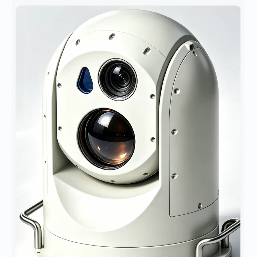 02 systemsEO/IR turretsTwo fixed-site turrets for persistent 60× optical and 75 mm thermal watch, with mount and sector coverage matched to the site.
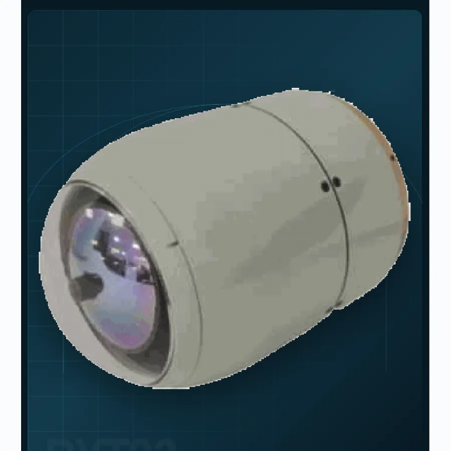 04 systemsPrecision seekersFour documented envelopes from Ø40 to Ø93 mm for terminal homing, target confirmation and guided-munition integration.
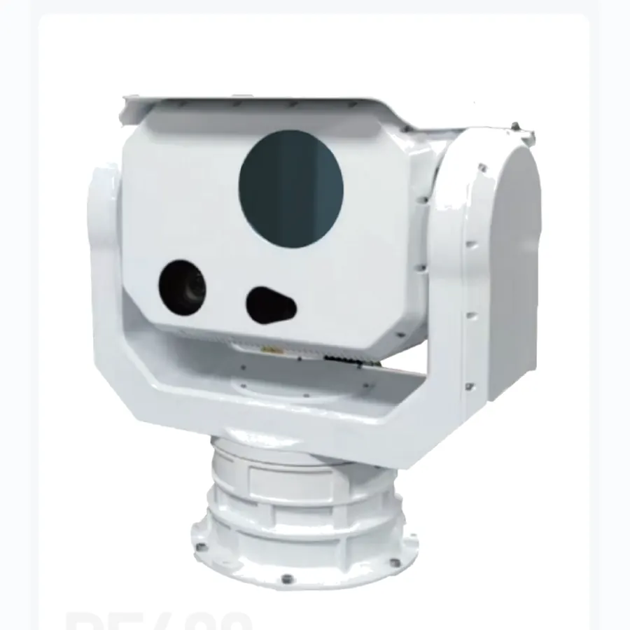 01 systemsCounter-UASOne 360° pedestal configured for rapid search, track acquisition and a clean handoff to an interceptor or effect layer.
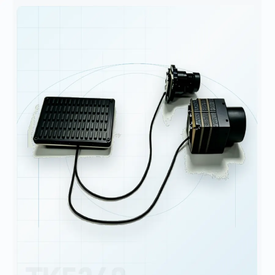 01 systemsAI coreAn onboard processing module for target recognition and track continuity when live video must be interpreted at the edge.
OEM and programme support
Share the platform, target set, range and interface constraints. We will map the relevant format and current documentation.